|
Cubical Quad Antenna Design | ||||||||||||||||||||||||||||||||||||||||||||||||||||||||||||||||||||||||||||||||||||||||
| By: Dr. Carl O.
Jelinek N6VNG
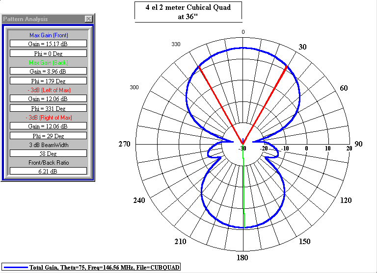
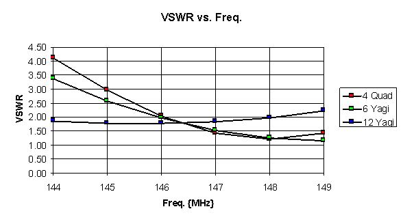
The frequency scaling formulas for Cubical Quad antennas are shown in Figure 1. Note that frequency is measured in Megahertz {MHz} and the total length of each element is measured in feet {ft}. The spacing of each element is the same and all directors are the same size. The gamma match uses a small air variable capacitor approximately the value given and an adjustable shorting bar at the end connected to the element. The antenna is tuned by adjusting the length of the shorting bar on the gamma match for minimum VSWR with the variable capacitor half engaged. Then adjust the capacitor for minimum VSWR at the mid band frequency. The enclosed EXCEL program can be used to determine the element lengths and the gamma match values for different frequencies. In general the design is robust and may be optimized for gain or front to back by adjusting the spacing of the elements. This antenna design has been built for both the ten and two meter versions and I have used them for T-Hunting and in two CVARC Field Day events with good results. Figures 2 and 3 show the calculated antenna patterns and performance. Table 1 shows an example output from the EXCEL Scaling program. Figure 4. Shows VSWR vs. Frequency for three different 2 meter antennas, a 4 element Quad, a 6 and a 12 element Yagi.
Figure 1. Cubical Quad Frequency Scaling Equations.
.
Figure 2. Elevation Pattern for the 4 element Cubical Quad 36" above a perfect ground
Figure 3. Azimuth Pattern for the 4 element Cubical Quad 36" above a perfect ground
Table 1. Cubical Quad Scaling Relationships
Figure 4. VSWR vs. Frequency for Three 2 Meter Antenna Designs. | ||||||||||||||||||||||||||||||||||||||||||||||||||||||||||||||||||||||||||||||||||||||||


